1965 Mustang Turn Signal Flasher Wiring Diagram

1871 1967 Ford Galaxie 500 Wiring Diagram Wiring Resources

Mustang Turn Signal Flasher Wiring Diagram Wiring Diagram

1965 Ford Mustang Electrical Schematics
0bf8733 Led Marker Turn Signal Flasher Wiring Diagram Wiring Library

1966 Mustang Emergency Flashers Come On With Turn Indicator Ford

1967 Mustang Turn Signal Switch Wiring Diagram 1967 Mustang 67
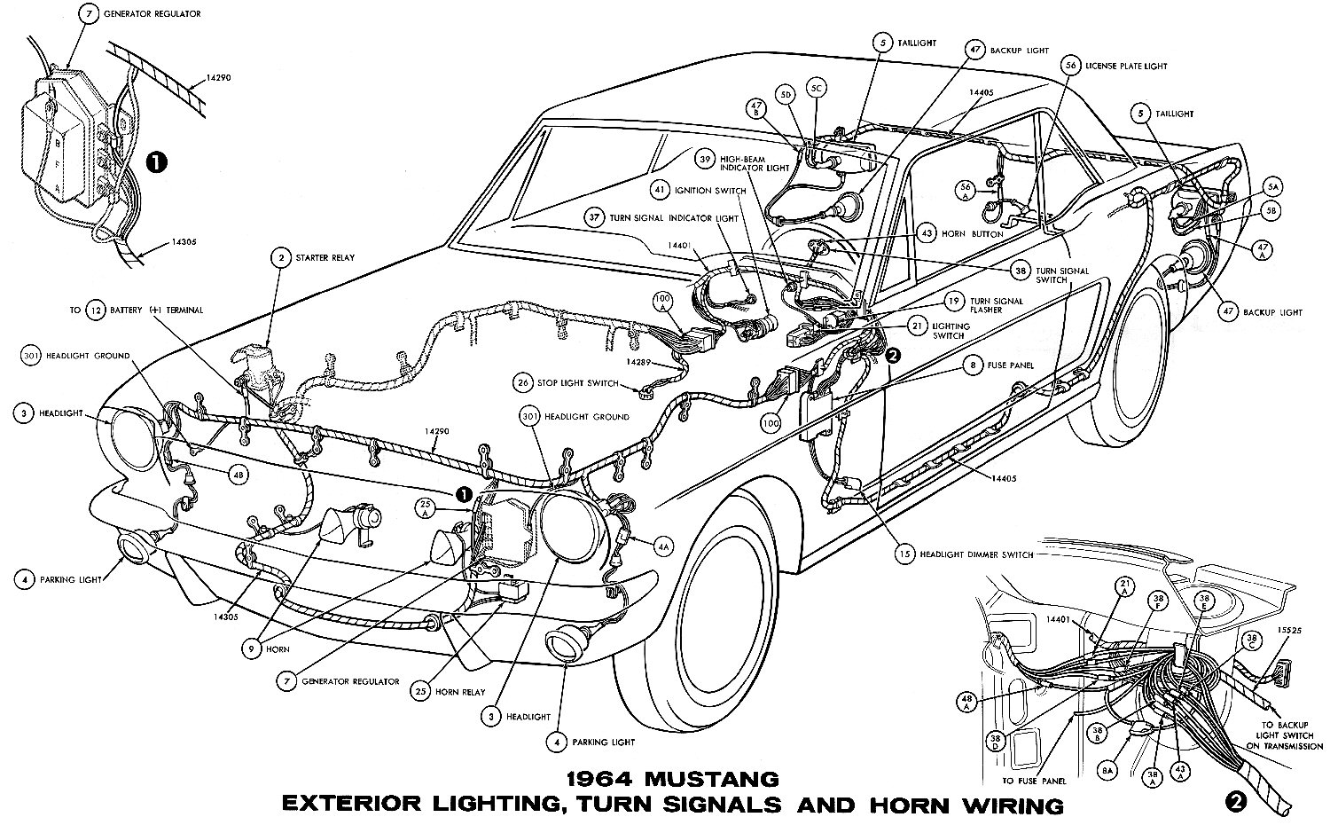
1966 mustang instrument panel instrument cluster connections wiper switch headlamp switch ignition switch and lighter 1966 mustang ignition starting and charging alternator regulator solenoid starter distributor plugs ammeter and starter neutral switch 1966 mustang exterior lighting turn signals and horns schematic headlamps parking lamps fog lights horns headlamp stop turn.
1965 mustang turn signal flasher wiring diagram. Taillights and backup lights. This turn signal and emergency flasher is the part that was used for turn signals but you can also use this part as a replacement for your emergency flashers. 1965 ford mustang electrical schematics adn diagrams. What the switch itself has is one yellow wire bringing power in for the horns one green wire bringing power in from the brake light switch one blue wire bringing power in from the flasher one blue yellow wire taking power out to the horns one white blue wire taking power out to the right front turn signal and right dash indicator one green white wire taking power out to the left front turn signal and left dash indicator one orange blue wire taking power to the right rear turn signal.
A wiring diagram is a streamlined conventional photographic representation of an electric circuit. 1979 2017 ford mustang diagrams troubleshooting documentation. 1965 mustang electrical information. The following wiring harness diagrams are available.
Exterior lights turn signal horns. Headlamps parking lamps horns. This setup is in my 1965 fastback with a scheduled build date of october 13th 1964. The following electrical drawings are available.
There is only one d hole stamped into my lower leftside dash instead of two because of the early production date. Aftermarket part reviews general discussion about muscle cars. 1965 mustang interior lights windshield wiper and gauges pictorial or schematic. The flasher unit is number 536 and is used for this application while the turn signal flasher is number 552.
Headlamp stop turn signal and ignition switches. It shows the parts of the circuit as streamlined shapes and also the power and also signal links in between the devices.

1965 F100 Wiring Diagram Ford Truck Technical Drawings And
946f5 65 Ranchero Neutral Safety Switch Wiring Diagram Wiring

The 16 Best Motorcycle Electrical Wiring Diagram For You
Wrg 1635 64 Ford Mustang Headlight Switch Wiring Diagram

How To Add Turn Signals And Wire Them Up The Basics

1965 Vw Wiring Diagram Volkswagen Wiring Diagrams Diagrama

23 Complex Wiring Diagram Online For You In 2020 Diagram

Husqvarna Mower Parts Diagram Di 2020

Super Clean Relay Board With Images Automotive Electrical

87 To 93 Mustang Fox Fuse Box Diagram 1987 1988 1989 1990

10 1982 Chevy Truck Fuse Box Diagram Truck Diagram Chevy

Mitsubishi Oem 2017 Mirage G4 Hood 5900a623 Cooling Unit

The 16 Best Motorcycle Electrical Wiring Diagram For You
